TR Design 3a
Concept
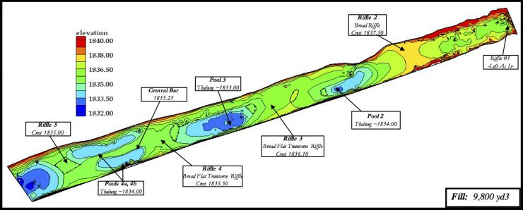
Using preliminary lessons learned from “stress testing” Designs 1 and 2 with 2D modeling and ecohydraulic analysis, Design 3a was a modification of Design 1 that had a significantly lower slope, longer riffles, and smaller, narrower pools. The riffle-pool relief was only increased from 0.78 to 0.88 m relative to the baseline, while the overall bed slope was decreased from 0.22% to 0.18%. The riffle-pool asymmetry was 2.2, which was similar to the previous designs, because the design still emphasized filling to build up riffles. The first riffle crest was shifted upstream due to its location in a constriction area and its crest elevation was lowered to reduce velocity and shear stress. The subsequent pool width was set to ~½ the channel width. The third riffle included a central bar complex based on a feature of that type designed and built on the lower Mokelumne River in 2001. The complex consists of upstream and downstream riffle crests linked by a narrow bar that is flanked by small pools. This complex is in the widest river section where there is at least some potential for shifting the focus of flood scour off of riffles and into pools. It was conjectured that the central bar and flanking pools would provide habitat heterogeneity in the face of fluctuating spawning flows and adult holding habitat proximal to spawning habitat. Also, the two small pools might serve as sediment traps to retain sediment placed upstream in this key spawning reach over time. Design 3a was estimated to require 7,493 m3 of gravel and cobble.
Design Map

Design Hypotheses
| Attributes | Riffle 2 | Pool 2 | Riffle 3 | Pool 3 |
| Hydraulic | Based on Design 1, but with crest at 1837.5 and exit pulled up of constriction to reduce total energy. Divergent flow over crest converging into pool. |
Constrictions at pool entrance and exit induce flow convergence, flow acceleration, and eddy formation adjacent to banks. |
Transverse-oblique riffle with flow convergence on riffle and divergence in proto-pool on right. Bump on crest to slow velocity and cause eddy downstream of it. |
Gradual entrance slope in proto-pool to dissipate momentum, extend spawning habitat and promote structural. |
| Geomorphic | Reduced scour potential compared with design 1. |
Constricted pool follows existing contour regime. Constricted pool downstream of broad riffle is conducive to riffle pool maintenance. |
Tracks existing contours. Crest length extended by oblique orientation. Divergent flow promotes spawning-flow riffle stability. |
Constricted pool tracks existing contours. Constriction helps riffle-pool maintenance. |
| Fisheries | -Spawning on river left of riffle and on riffle crest. -Increased fry habitat along riffle periphery. |
-Adult holding habitat in pool. -Rearing habitat channel margin. -Spawning on pool benches. |
-Spawning habitat on riffle. -Pool-exit rim shape promotes gravel oxygenation and is ideal habitat. -Increased fry habitat along riffle periphery. |
-Adult holding habitat in pool. -Rearing habitat channel margin. -Spawning on pool benches. |
| Attributes | Riffle 4 | Central Bar / depressions 4a,b |
Riffle 5 |
| Hydraulic | Broad flat riffle with shallow, moderate flow optimized for spawning. |
Divergent flow fields around bar, convergence within both depressions. Additional spawning habitat with high gravel-volume efficiency. |
Broad flat riffle with shallow, moderate flow optimized for spawning. Improved oxygenation due to 2 depression exits. |
| Geomorphic | At spawning Q, velocity is below threshold for scour. |
Depressions will serve as traps for upstream sediments to keep them in the reach for continued spawning use. |
At spawning Q, velocity is below threshold for scour. |
| Fisheries | -Spawning on entire riffle. -Rearing along riffle periphery. |
-Spawning on pool exit slopes and on bar top. -Adult holding in depressions. |
-Spawning on entire riffle. -Rearing along riffle periphery. |
Design Testing with FESWMS 2D Model
System response was evaluated in terms of flow pattern, fish habitat quality, and sediment transport regime at three discharges within the regulated range permitted by operational rules at the time. At the links below, the results are shown for two of those discharges: (1) a typical baseflow (300 cfs) present during most of the year when fish are spawning and embryos are incubating and (2) the peak regulated flood discharge released by the dam at that time (6000 cfs).
Click links below to see model results:


