LMR 2001 Site
LMR 2001 Preliminary Planning
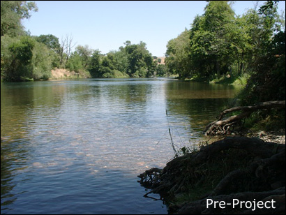
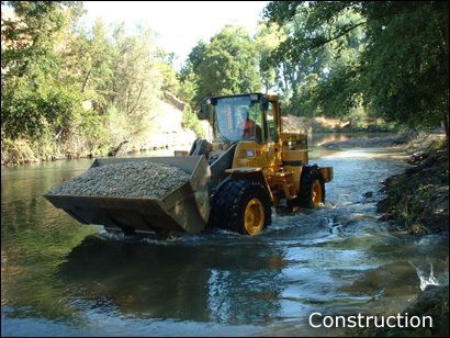
During winter 2001, EBMUD identified a degraded riffle in the MRDUA downstream of the 1999 site and Murphy Creek that they desired to rehabilitate based on habitat, engineering, hydrogeomorphic, and accessibility criteria. This project was the first to use the SHIRA framework . Based on pre- project study, it was determined that the primary goal of the project would be to improve exist ing low quality habitat to medium and high quality habitat by gravel add it ion. Designs were based on an anticipated ~ 1500 short tons of washed floodplain gravels and cobbles, but only 794 tons ended up being available, necessitating on-the-spot design reductions. Subsequent efforts have always used staged designs to avoid this problem.
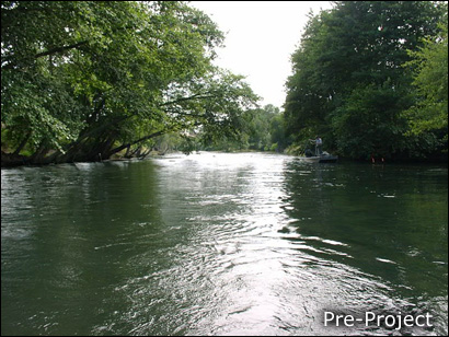
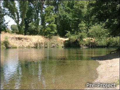
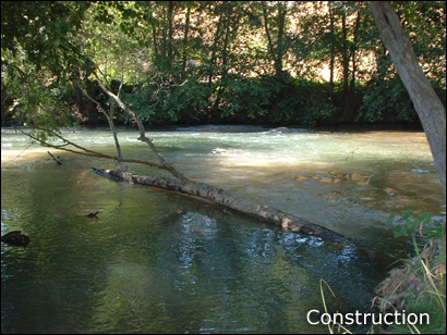
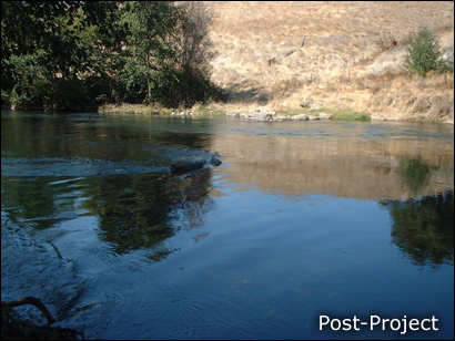
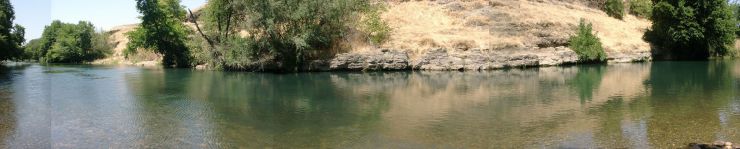
Below is a wide-angle view of the 2001 project site before construction.
LMR 2001 Pre-Project DCM
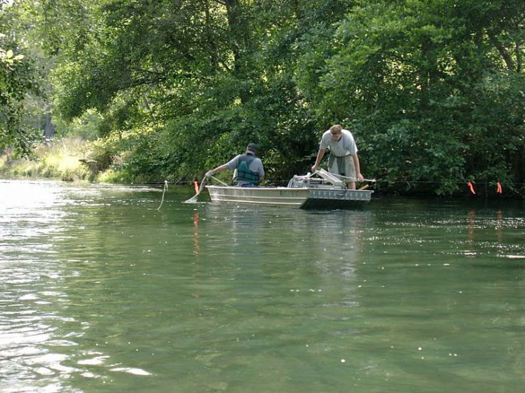
Channel topography, water depth, water surface elevation, velocity, and substrate sizes were measured on-site. 2D model parameters including eddy viscosity and bed roughness were estimated based on field observation and data analysis. Flow patterns were imaged using floating ropes.
LMR 2001 Pre-Project Geomorphic Analyses
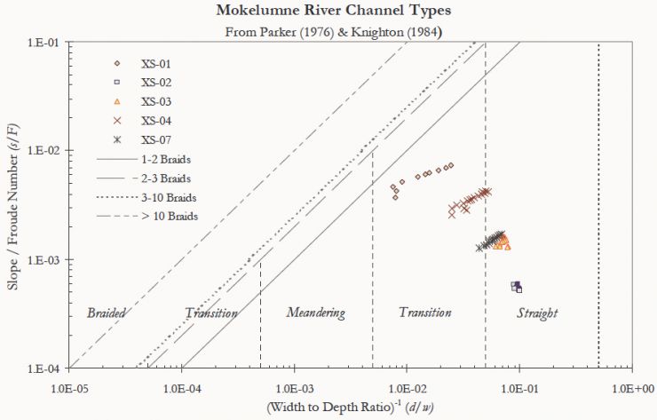
Several geomorphic analyses were performed for 5 cross-sections in the reach. For example, the graph bellow shows the application of a quantitative river classification analysis to better understand the process-form linkages for the baseline condition of the site.
LMR 2001 Pre-Project Modeling
This degraded pool-riffle unit features an undercut bedrock outer bend and a riffle with so much gravel depletion that bedrock is exposed. The channel width has been constricted due to vegetation encroachment. The upstream riffle is an artificial placement that uses a "chevron" morphology typical of earlier rehabilitation efforts.
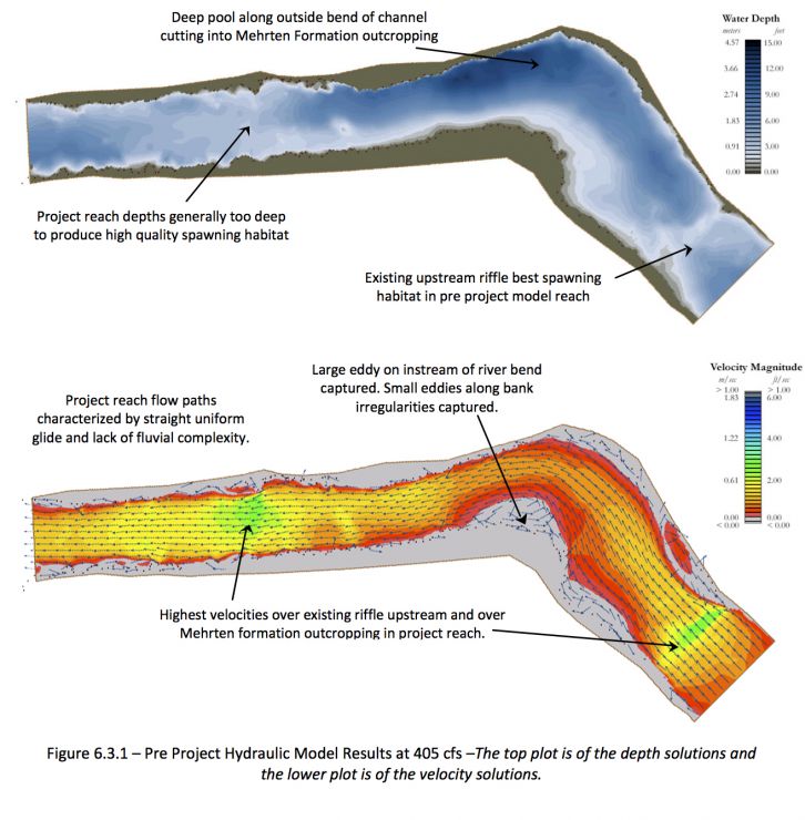
The pre project hydrodynamic model results illuminate the reasons why high quality spawning habitat is generally absent in the project reach. Depths through the project reach are too deep and velocities are too low to produce high quality spawning habitat. Furthermore, the flow paths through the pre project reach are characterized by a glide lacking fluvial complexity. The most optimal spawning conditions are found in an existing riffle at the upstream end of the project reach (previous EBMUD habitat enhancement site).
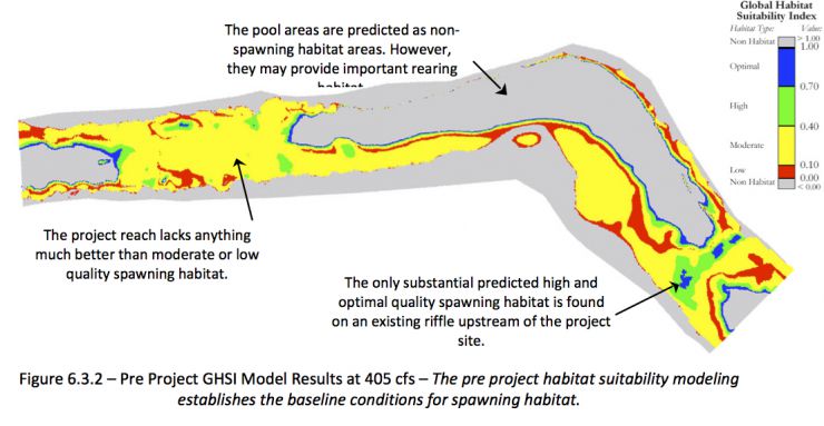
The pre project GHSI modeling results confirm the lack of substantial areas of optimal or high quality spawning habitat. Roughly 56 percent of the model reach was found to be non spawning habitat. Of the actual spawning habitat, only 2.8 percent was found to be of optimal quality, 7.5 percent was of high quality, 23.1 percent was of moderate quality and 67.6 percent was of low quality.
The pre project modeling results show negligible potential for entrainment of gravels of existing gravels off the bed at a discharge of 11.46 cumecs (405 cfs). Although this suggests sediment entrainment at spawning flows is negligible, it does not imply that sediment entrainment will not occur at higher flows.


LMR 2001 Design Concepts
Twelve alternative scenarios for 2001 gravel placement were designed to compare against the existing condition. The different channel configuration types tested included alternate bars, peripheral bars, pool -constrict ion bars, central bar, multiple longitudinal bars, flat riffle, and complex bar assemblages. All designs used large, coherent bed features that were thought to offer high quality contiguous habitat while also limiting isolated protrusions susceptible to erosion. Because any backwater effect caused by the gravel fill might impact pre-existing artificial riffle projects upstream of the 2001 site, the model domain included the pool and riff le upstream of the site to evaluate impacts . Downstream of the site the channel broadens significantly due to historic instream activities, so there was no need to extend models in that direction. The primary objective of the design process was to determine the hydrogeomorphic and ecologic functionality of different potential designs prior to implementation, thereby reducing potential problems.
LMR 2001 Design 2
The Alternate Bar (tight spacing) scenario was the first design scenario modeled. The basic principle behind the design was to increase the habitat area without wasting large amounts of gravel in the pool upstream of cross section three. For this reason, the vast majority of the gravel was placed downstream of cross section four. This design was an attempt to construct an alternate bar design, as is typically found in alluvial rivers with low sinuosity. However, given the upstream pool constraint and the downstream boundary of the project, bar spacing was confined to a short reach of river only 2.5 to 3 channel widths apart. Geomorphologists have observed the occurrence of these types of alternate bars at spacing from 4 to 10 channel widths (Rosgen, 1995). For this reason, the scenario was called (tight-spacing). Roughly 510 m3 of gravel were specified in Design Scenario 02 with a maximum fill depth of 1.15 m.
Depths were predicted to range from 0- 13' for the reach, with the alternate bars partially submerged and the intervening riffle crest having very shallow, skimming flow.
Velocity magnitude was predicted to range from 0-4 ft/s, with the highest values over the riffle crest where flow was very shallow. The velocity over the upstream riffle crest is reduced by =1-1.5 ft/s in this design to due backwater effects from the gravel fill.
Fluvial complexity is not enhanced, as velocity vectors indicate flow paths similar to that of the pre-project condition without any large secondary flow cells or eddies being formed.
Design scenario 02 slightly decreased the total area of spawning habitat within the model reach from 4552 m2 to 4471 m2. The scenario ranks seventh in terms of its efficiency at producing total spawning habitat areas per cubic meter of gravel (-0.16 m2 per m3 of gravel); ranks eighth in terms of efficiency of producing optimal habitat areas (-0.20 m2 per m3 of gravel); and ranks eighth in terms of its production of optimal and high quality habitat (0.12 m2 per m3 of gravel). The "bathtub# rings of medium and high quality habitat around the pools are an artifact of the empirical equation used to generate GHSI in 2001.
8 mm gravels are predicted to be unlikely to scour for most of the reach with this discharge, except on the riffle crest where infrequent, strong turbulent burst could yield forces exceeding the average predicted conditions. 32 mm and coarser sized bed materials are predicted to be unlikely to scour anywhere on-site at this discharge.
LMR 2001 Design 3
The third design scenario (constricted riffle) was intended to be an improvement of the second design scenario. The hope being that by raising the elevation of the riffle between the two alternate bars and placing boulders on both edges of the channel, velocities would increase through the riffle and better spawning habitat would arise. Although the modeling results will show the configuration did increase velocities, it increased them so much that supercritical flows were produced. Thus, the area designed as the primary spawning habitat was pushed into the realm of sediment entrainment during spawning flows, which clearly is not desirable. Design Scenario 03 reached a maximum fill depth of 1.6 m with 1016 m3 of gravel specified.
Water depth was predicted to range from 0-13', with the alternate bars partially submerged and the intervening riffle crest having very shallow, skimming flow over a very large area. because of the high gravel fill height, the upstream riffle crest was drowned out, which was impermissible.

The constriction at the riffle was predicted to great ly increase velocities by more than 5 ft/s over the crest. This yielded supercritical flow. Conversely, the significant backwater effect upstream of the grave l fill reduced upstream velocities below the desired magnitude.
The constriction at the riffle was predicted to cause strong flow convergence over the riffle crest and strong divergence over the riffle exit. The downstream alternate bar created a constrict ion that forced the flow to re-converge on river left, which induced a strong secondary flow cell over the bar. Also, strong shear along the riffle flanks yielded fast eddies on both banks.
Design scenario 03 produced a slight decrease in the total area of spawning habitat within the model reach from 4552 m2 to 4115.9 m2• High quality habitat is limited to a narrow band along the edge of the alternate bar. The "bathtub" rings of medium and high quality habitat around the pools are an artifact of the empirical equation used to generate GHSI in 2001.
8 mm grave ls were predicted to definitely scour over much of the riffle at this discharge. Flow constrictions were found to be important causes of local scour based on this scenario. 32 mm grave ls were predicted to definitely scour over much of the riff le at this discharge. Flow constrictions were found to be important causes of local scour based on this scenario. The median particle size of this gravel/cobble bed was predicted to mobilize over the constricted riffle crest and part of the broader riffle area at this discharge. 64 mm cobbles were predicted to definitely scour over part of the riffle where convective acceleration was localized near flow constrictions at this discharge. 128 mm cobbles were predicted to scour in the immediate area where convective acceleration was localized near flow constrictions at this discharge. Intermittent scour due to turbulent bursts above the mean prediction is likely over the riffle.
LMR 2001 Design 5
A fourth design scenario was developed that produced a large, broad flat riffle. Unfortunately, it used more than twice the gravel available to the project. The fifth design scenario again created a large flat riffle but accomplished it within the realm of gravel available for this project. 961 m3 of gravel were used with a maximum fill depth of 1.5 m to produce a broad flat riffle, which would allow flow to diverge across it, while also providing a large contiguous area of high quality spawning habitat. No boulders were used in this design as to focus the efforts entirely on the configuration of gravel. While the design was effective in terms of producing habitat, it failed to produce much fluvial complexity or diversity. Existing channel widths through the model reach were constant through the pool and existing glide. Channel banks are armored by bedrock outcroppings and well established riparian vegetation. Thus, widening the channel was not an alternative. To produce a broad flat riffle, as in this design, the riffle had to be constructed uniformly across the channel. While no apparent change in channel top width was induced between the project riffle and the existing pool, the pool already was somewhat constricted to river right along the Mehrten formation.
Water depths were predicted to range from 0- 13' for the reach, with the broad flat riffle having depths of 0-2'. Water depth over the upstream riffle was increased by 0.5 - 1'.
The broad flat riffle was predicted to greatly increase velocities over the main riffle, yield ing a large desirable area with velocities of 2-4.S ft/s. The upstream riffle had its velocity reduced by = 1-1.5 ft/s by the backwater effect.
The broad flat riffle was predicted to induce two strong secondary flow cells on both sides of the channel in the pool downstream of the riffle. Fluvial complexity is increased slightly over pre project conditions but still exhibits a generally uniform flow pattern, because there was minimal change to overall channel width.
Design scenario OS was predicted to yield 5 times more high-quality habitat and 2.3 times more medium quality habitat than the pre-project condition. The "bathtub" rings of medium and high quality habitat around the pools are an artifact of the empirical equation used to generate GHSI in 2001.
8 mm gravels are predicted to scour over the highest velocity areas on the riffle at this discharge. Other riffle areas will be subjected to intermittent scour where infrequent, strong turbulent bursts could yield forces exceeding the average predicted conditions. 32 mm gravels are predicted to be unlikely to scour anywhere on-site at this discharge. The median, 64, and 128 mm particle sizes of this gravel/cobble bed are predicted to be unlikely to mobilize anywhere on-site at this discharge.

LMR 2001 Design 6
The sixth design scenario (constricted pools) sought to maintain a broad riffle (keeping much of the contiguous spawning habitat from the fifth design scenario), but in addition attempted to further constrict the width of the pools both upstream and downstream of the riffle. Gravel was specified to accentuate the point bar upstream of the riffle on river left and specified downstream of the riffle on river right to create an alternate bar. The bars were placed roughly 4 channel widths apart. Both bars acted to constrict the width of the channel at the pools while allowing the width to expand across the entire width of the channel through the riffle. The design allows the bulk of flow to switch from river right to river left as it diverges across the riffle. This was intended to compliment the transitional classification of the channel between a straight and meandering river. The alternate bar pattern introduces some variation in the channel geomorphology which may be consistent with the concept of a river that may fall between meandering through its floodplain and pointing straight as a flood control canal. 956 m3 of gravel was consumed in this design which reached a maximum fill depth of 1.4 m.
Water depths were predicted to range from 0- 13' for the reach, wit h the broad flat riffle having depths of 0-2'. Water depth over the upstream riffle was increased by only =0.5' . The pool-constriction bars are submerged by very shallow.
The broad flat riffle was predicted to increase velocities over the main riffle, but not by as much as for Design 05. This design yielded a large desirable area with velocities of 2-3.5 ft/s. The upstream riffle had its velocity reduced by only ~0.5 ft/s by the backwater effect.
Because of the addition of pool-constrict ion bars, the flow was predicted to converge over the primary pool, diverge over the main riffle's entrance, and then converge again over the riffle exit. The thalweg meandered from river right to river left over the riffle, as desired. A secondary flow cell developed over the downstream constrict ion bar due to the migration of the thalweg around it. This scenario illustrates the utility of constriction bars in controlling flow location and flow convergence/divergence, which is a necessary step toward creating a self-sustainable geomorphic unit.
Design 06 produced an increase in the total area of spawning habitat within the model reach from 4552 m2 to 4640 m2 . The sixth design produced a large contiguous area of high quality spawning habitat across the broad riffle. High and medium quality habitat areas increased by factors of 4.3 and 1.8, respectively. The "bathtub" rings of medium and high quality habitat around the pools are an artifact of the empirical equation used to generate GHSI in 2001.
8 mm gravels are predicted to be subjected to intermittent scour where infrequent, strong turbulent bursts could yield forces exceeding the average predicted conditions over the broad flat riffle at this discharge. 32 mm and coarser sized bed materials are predicted to be unlikely to scour anywhere on-site at this discharge.

LMR 2001 Design 7
The seventh design scenario represents a departure from the approach of the previous design scenarios. The previous design scenarios all revolved around some sort of single riffle created by raising the bed elevation with gravel. A delicate balance between the overall slope of the reach and the spacing of pool riffle sequences limits the effectiveness of a constructed bed form at increasing velocities. In other words, inducing a steeper gradient and higher velocities by raising the bed in the project reach, will propagate a backwater effect upstream, which may drown out productive spawning habitat in riffles upstream. The existing riffle located upstream of the project was declining in spawning habitat quality due to backwater effects created by the earlier design scenarios.
In an effort to minimize the backwater effect and develop a higher degree of fluvial complexity, design seven was developed. This scenario used 865 m3 of gravel and a maximum fill depth of 1.4 m. The design raised the bed in two riffles to an elevation slightly lower than the single riffle in previous designs. A central bar in the middle of the channel was designed to bridge the upper and lower riffles and further divide the flow diverging across the upstream riffle. The downstream riffle was designed as a wide riffle over which the flow separated by the bar may further diverge. If divergent flow across riffles does indeed lead to deposition of coarse-grained sediment at high flows and preservation of riffles (Thompson, 1999), such a design could potentially be self-sustaining. Bedload transport entraining gravels from upstream portions of the project might deposit those gravels along the downstream riffle.
Existing deeper areas along both sides of the central bar were maintained as pools to serve several purposes. First, recirculating eddies induced by the constriction of flow through the pools could in fact lead to further aggradation of sediment on the exit slope of the pools and over the downstream riffle. Secondly, designs with only one riffle introduce only one pool-exit slope. Pool exit slopes are known to be sites where preferential spawning occurs due to downwelling of water. Thus, buy incorporating two small pools into the design, a total of three pool-exit slopes are created by the project. Finally, the two pools increase the diversity of bed forms and create important rearing habitat close to spawning sites. Such diversity of habitat types may be important factors to provide spawning females with areas to conserve energy or hide from predators, while still keeping an eye on her redd nest.
Water depths were predicted to range from 0- 13', with a complex spatial pattern reflecting the pattern of gravel fill. Water depth over the upstream riffle was increased by only ~0.5'.
Velocity magnitude was predicted to be highest over the 2 flat riffle areas (~3 -4 ft/s). The central bar had a low velocity and the peripheral pools had intermediate velocities. The upstream riffle had its velocity reduced by only ~0.5 ft/s by the backwater effect.
The upstream pool-constriction bar converged flow over the pool and then diverged it over the first riffle crest, yielding desirable and stable velocities. The thalweg then diverges around the central bar yielding two convergent, deep, fast threads through the two peripheral pools so that sediment may settle out there. The flow then diverges out of the two constricted pools and over the downstream riffle. Finally, it converges into the tail pool. The thalweg begins on river right and ends on river left, yielding a secondary flow cell over the smaller downstream pool-constricting bar.
Design scenario 07 was predicted to produce an increase in the total area of spawning habitat with in the model reach from 4552 m2 to 4699 m2 . High and medium quality habitats were predicted to increase by factors of 3.4 and 2, respectively.
8 mm grave ls are predicted to be subjected to intermittent scour over the downstream flat riffle where infrequent, strong turbulent bursts could yield forces exceeding the average predicted conditions at this discharge. The other riffle areas were predicted to be unlikely to have their 8 mm gravels scour. 32 mm and coarser-sized bed materials are predicted to be unlikely to scour anywhere on-site at this discharge.


LMR 2001 Design 8
The eighth design scenario is not an attempt at a braided channel, but instead an attempt to promote fluvial complexity while producing higher quality spawning habitat. Naturally braided rivers exhibit much higher gradients then the lower Mokelumne and are accustomed to much higher sediment supplies. Two gravel braids were placed from cross section four downstream to cross-section seven. The three chutes created surrounding the braids take on the appearance of a braided channel. The chutes themselves were partially filled with gravel to achieve optimum depths while maintaining slightly deeper pools within them. If the design is successful at producing spawning habitat, it should be extremely efficient as it only consumes 617 m3 of gravel and has a maximum fill depth of 1.2 m. Gravel was again used upstream to constrict flow to the pool and provide ample construction access for the front end loader. The design should also be effective at minimizing the backwater effect as the chutes act as breaks instead of a riffle which acts as a dam.
Water depth was predicted to range from 0-13' with significant depth reductions over the riffle. The lack of a cross-channel riffle crest was predicted to keep the water depth of the upstream riffle at nearly the same level as it was pre-project.
Velocity magnitude was predicted to be highest through the chutes (2-3 ft/s) and lower over bar tops (1-2 ft/s). Because this design did not include a significantly raised riffle crest, its velocities are relatively lower that those for other designs. Also, this resulted in a minimal backwater effect, so the upstream riffle would receive little impact.
Flow was predicted to be converged through the upstream pool, diverged over the riffle entrance, and then converged into three chutes. At the downstream end, the flow converged in a nearly central thalweg with a peripheral secondary cell on each side of it.
Design scenario 08 produced a small increase in total area of spawning habitat of 5 m2. High and medium quality habitat areas increased by factors of 1.8 and 1.7, respectively. Notice that the optimal quality habitat pockets correspond to the tops and exits of the braids whereas the chutes only produce moderate quality habitat. The "bathtub" rings of medium and high quality habitat around the pools are an artifact of the empirical equation used to generate GHSI in 2001.
All 8 mm and larger bed material sizes are predicted to be unlikely to scour anywhere on-site at this discharge.


LMR 2001 Design 9
The ninth design scenario tried to follow the trend of seven and eight by not creating a backwater effect upstream of the riffle thus drowning out the 1996 riffle upstream of the project. Unlike scenarios seven and eight, where most of the gravel was expended in the center of the channel creating bars or braids, scenario nine attempted to increase habitat area by increasing the elevation along the periphery of the channel by creating benches. Its overall effectiveness was mixed as it created large amounts of moderate quality habitat and minimal amounts of optimal habitat. This is due to the fact that decreasing depth does not always increase velocity. Here, the bars act almost like an inset floodplain, where velocities are actually to low to produce optimal habitat. The design scenario is instructive because it illustrates that shallow depths, without a significant hydraulic gradient generally can not raise velocities high enough to produce optimal spawning habitat.

Water depths ranged from 0-13', with the primary pool and riffle both being constricted by peripheral bars. The lack of a cross-channel riffle crest was predicted to keep the water depth of the upstream riffle at nearly the same level as it was pre-project.
The effect of the riffle constriction was to generate high velocities in the the center of the channel over the riffle. Because water was not backed up upstream, the magnitude of this peak in velocity was not severe, but it would expect to be greater with increasing discharge.
This scenario converged water into the upstream pool and then maintained that channel center convergence through the entire length of the reach. Secondary flow cells are predicted at the end of the lateral bars where there is a rapid width expansion.

Design scenario 09 decreased the total area of spawning habitat within the model reach from 4552 m2 to 4535 m2. High and medium quality habitat areas increased by factors of 1.2 and 2.3, respectively. The central chute is a bit too deep and fast to be good quality spawning habitat, while the lateral bars are too sluggish to be the best possible habitat. The "bathtub" rings of medium and high quality habitat around the pools are an artifact of the empirical equation used to generate GHS! in 2001.
All 8 mm and coarser bed material sizes are predicted to be unlikely to scour anywhere on-site at this discharge.


LMR Design 12
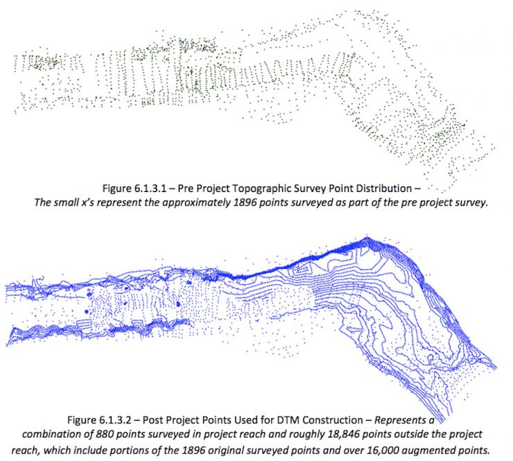
The final design was based off a refinement of Design 07. Design 07 was selected as the most desirable design scenario for a mix of geomorphic, ecologic reasons and the modeling results. Recall Design 07 only used 865 m3 of gravel and 1146 m3 was thought to be available for construction. The final design modified the design scenario to consume the additional 281 m3 of gravel. This was done by extending the riffle features of the design slightly upstream and downstream of their original locations and by increasing the tail of the existing riffle located upstream of the project. The diagram below shows the final grading plan in the project reach and the associated point output from the DTM used for mesh discretization. Similar point outputs were created for each of the design scenarios based off a combination of point augmentation techniques including grid, contour and original survey data.

Water depths were predicted to range form 0-13', with a complex spatial pattern. The depth is greater over the upstream flat section of the main riffle and very shallow over its downstream flat section. A compromise riffle crest elevation yielded =0.5 -0.75' depth increase over the upstream riffle.

Velocity magnitude ranged from 0-4.2 ft/s, with the highest velocity over the shallow downstream flat riffle section. The velocity over the upstream riffle was decreased by 0.5 -1 ft/s.
The flow pattern was predicted to converge in the upstream constricted pool, diverge over riffle entrance, and then split into two threads around the central bar and over the peripheral pools. Flow then diverged out of the pools and onto the large flat riffle section. Overall, flow migrated form river right over the pool to river left exiting the riffle, as desired. A strong secondary flow cell in the tail pool constricts the flow through the left half of the tail pool.
The Final Design scenario 12 increased the total area of spawning habitat within the model reach from 4552 m2 to 4883 m2. High and medium quality habitat areas increased by factors of 2.9 and 2.9, respectively. In marginal terms, 6.26 m2 of habitat were predicted to be generated for each m3 of gravel added. Some habitat degradation to the upstream riffle was predicted, but this was highly offset by the predicted gains to the rehabilitated area. The "bathtub" rings of medium and high quality habitat around the pools are an artifact of the empirical equation used to generate GHSI in 2001.
8 mm grave ls are predicted to be subjected to intermittent scour where infrequent, strong turbulent bursts could yield forces exceeding the average predicted conditions over the downstream broad, flat riffle section at this discharge. The rest of the site is not predicted to have its 8 mm gravels scour. 32 mm and coarser-sized bed materials are predicted to be unlikely to scour anywhere on-site at this discharge.

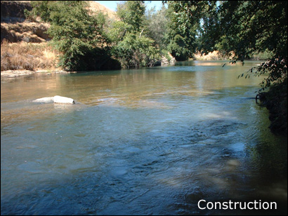
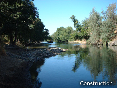
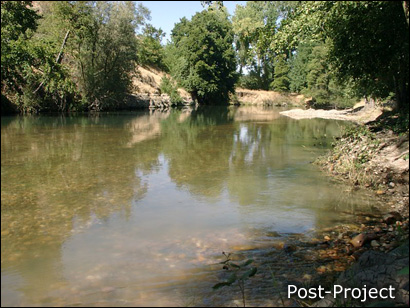
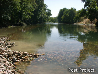
LMR 2001 As-Built Analysis
Significantly less gravel was brought to the site for construction than had been anticipated, thus yielding insufficient gravel fill to construct the downstream broad, flat riffle. Nevertheless, the post -project condition yielded the highest gravel efficiency for habitat enhancement of any hypothetical design. Boulders placed in the channel as part of the rehabilitation were included in the 2D model analysis
Water depths were successfully decreased over the riffle to yield the desired range of 0-2 ft for a large area. A small increase in depth occurred over the upstream riffle ( <0.5').
Velocity magnitude was predicted to be 2-3.5 ft/s for most of the riffle area. Because the riffle exit was not built to the design specification such that it ended abruptly with a steep slope, velocity increases significantly over that region to 3.5-5 ft/s. The upstream riffle experienced a decrease of 0.5-0. 75 ft/s, but was still within the good range for spawning.
The flow pattern was predicted to reasonably match the desired outcome, except near the end of the project where insufficient gravel was added. Because the downstream riffle had a horseshoe-shaped riffle exit, flow converged over the center of the channel rather than along river left . A secondary flow cell was still generated on the river right side of the tail pool, but without the downstream pool-constriction bar, it was smaller than desired. Complex flow patterns around boulders were resolved, but are not visible on t his image.
The post-project habitat was predicted to increase total habitat by 158 m2 . High and medium quality habitat areas increased by factors of 2. 7 and 2.4, respectively. In marginal terms, 8.83 m2 of habitat were generated for each m3 of gravel added, which was the most efficient design studied. Some habitat degradation to the upstream riffle was evident. Mid-depth low quality habitat areas were submerged further yielding poor quality spawning habitat, but this was highly offset by the significant gains of high and medium quality habitat. The "bathtub" rings of medium and high quality habitat around the pools are an artifact of the empirical equation used to generate GHSI in 2001.
8 mm gravels are predicted to be unlikely to scour for most of the reach at this discharge, except in convective acceleration zones adjacent to boulders and at the over-steepened riffle exit where infrequent, strong turbulent burst could yield forces exceeding the average predicted conditions. 32 mm and coarser bed materials are predicted to be unlikely to scour anywhere on-site at this discharge.