TR Design 5
Concept
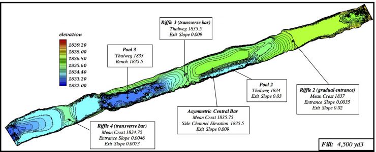
The goal for Design 5 was to have the lowest change in riffle-pool relief to limit the amount of gravel fill, while still maintaining the same slope as in the baseline topography as well as to increase fluvial complexity and spawning habitat, while minimizing low-flow scour of that habitat. The riffle-pool amplitude and asymmetry amongst morphologic units were 0.75 m and 12.01, respectively. As in Design 4, the channel was widened 3 m on the right to remove encroaching vegetation, increase channel area, and increase marginal areas of low velocity for fry habitat. In this design, the first riffle was significantly lengthened, but given a lower crest elevation. Based on preliminary benefits of a central bar observed in Design Three, a central bar was placed immediately downstream with a fast and slow velocity chute on its sides. It was modified here to split the flow into two parallel paths- a fast, deep chute and pool on the left and a slow, shallow glide (highlighting steelhead spawning and rearing) on the right. Consequently, the majority of flow was anticipated to go through the chute and pool, hopefully enabling high flows to scour that out and maintain it as a chute-pool unit. Downstream of the central bar, the pool was left deeper, with the exception of a narrow bench for fry on river right. The last riffle was designed with a short accentuated crest bounded upstream and downstream by long, gradual entrance and exit slopes. The exit slope and approach slopes were graded to dissipate incoming and outgoing velocities. Design 5 was estimated to need only 3,440 m3 of gravel and cobble.
Design Map
Design Hypotheses
| Attributes | Riffle 2 | CentralBar/ Pool 2 | Riffle 3 |
| Hydraulic | Existing riffle widened to promote flow divergence. Preceding pool exit slope graded to gradually dissipate high velocities. |
Majority of flow will converge into pool 2. Some flow will diverge around central bar and into river right side channel. Bar top will have low velocity. |
Transverse bar to control velocity out of riffle 2 and diverge thalweg over full channel width. |
| Geomorphic | Flow divergence through upstream pool exit will diminish scour at lower flows. |
Thalweg through pool 2, which is constricted to focus scour to aid passage of sediment.Flow divergence out of pool 2. |
At spawning Q, velocity is below threshold for scour. |
| Fisheries | -Majority of spawning on gradual riffle entrance. -Some spawning on crest and riffle . Grade front loader tracks to yield artificial-redd micro-topography. -Increased fry habitat along periphery of riffle. |
-Low-velocity, low-depth spawning and fry habitat on central bar top. Spawning in side channel. -Fry habitat along side channel margin. -Adult holding in side channel and pool bottom. |
-Spawning on riffle crest. |
| Attributes | Pool 3 | Riffle 4 |
| Hydraulic | Constrictions at pool entrance and pool exit will induce flow convergence, flow acceleration, and eddy formation adjacent to banks. Bench morphology on river right for spawning and rearing. |
Broad flat riffle with higher transverse bar. Upstream and downstream benches optimized for spawning. Minimal tail end flow convergence. |
| Geomorphic | Pool uses existing contour regime. Constricted thalweg and peripheral benches promote self-maintenance. |
At spawning Q, velocity is below threshold for scour. Exit slope graded gradually to minimize flow convergence and riffle-exit scour. |
| Fisheries | -Adult holding habitat in pool. -Fry habitat along river right bank and bench. -Spawning on peripheral bench. |
-Spawning on entire riffle and entrance and exit slopes. -Fry habitat along channel margin. |
Design Testing with FESWMS 2D Model
System response was evaluated in terms of flow pattern, fish habitat quality, and sediment transport regime at three discharges within the regulated range permitted by operational rules at the time. At the links below, the results are shown for two of those discharges: (1) a typical baseflow (300 cfs) present during most of the year when fish are spawning and embryos are incubating and (2) the peak regulated flood discharge released by the dam at that time (6000 cfs).
Click links below to see model results:
Design 5 2D Model Results

Design 5 2D Model Results