LMR 2002 Site
LMR 2002 Preliminary Planning
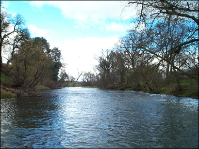
During winter and spring 2002 , EBMUD and UCD performed a reconnaissance of the LMR to identify a degraded riffle -pool- riffle -pool unit with adequate slope to avoid backwater impacts and provide enough energy head for rehabilitation. Also, a site with an accessible floodplain for modeling higher flows was desired. Previous habitat, engineering, hydrogeomorphic, and accessibility criteria were also employed . Based on pre -project study, the primary goal of the project was to improve existing low quality habitat to medium and high quality habitat by gravel addition and to employ and evaluate an array of habitat heterogeneity elements . Staged designs were based on an anticipated ~2100 short tons of washed floodplain gravel and cobble, and that amount was actually available, due to use of a reliable gravel source.
LMR 2002 Pre-Project Characterization
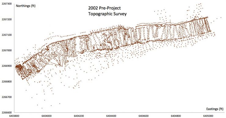
Channel topography, water depth, water surface elevation, velocity, and substrate sizes were measured on-site. Geomorphic analysis was done analyzing the site at several cross-sections using the same methods as used in 2001. 2D model parameters including eddy viscosity and bed roughness were estimated based on field observation and data analysis. 2D model validation data was collected.
LMR 2002 2D Modeling
One aspect that sets SHIRA apart from other river rehabilitation frameworks is that it uses predictive 2D model ing to assess the design hypotheses used in each design scenario in terms of hydrodynamics, bed scour, and habitat availability.
2D model predictions are presented for pre and post -project conditions as well as for conditions in the 3 alternative designs. Models were run for the spawning flow only because no rating curve data was available for the site at higher flows due to minimal releases in the 2 years prior to the project. However, subsequent releases have allowed for model analyses up to 2500 cfs, which are not presented at this time. Brief comments on each spawning flow analysis are provided.
LMR 2002 Pre-Project Modeling
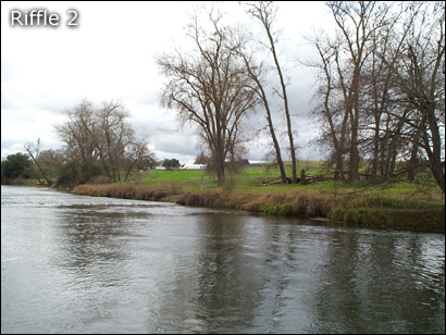
In its pre-existing state, the 2002 site was composed of an artificial cattle crossing serving as the upper "riffle", followed by a long glide, followed by a growing channel constriction induced by an island composed of fine deposits, followed by a riffle, followed by point bar and pool.
The units in all plots below are American customary (ft, ft/s).
Water depths were predicted to range from 0-7 .3'. The glide area with depths of 2.5-5.5' was selected as the primary region for gravel addition, with a staged secondary site at the lower riffle.
Velocity magnitude was predicted to range from 0-4 ft/s, with peaks over the cattle crossing and adjacent to the two major channel constrictions. Lows occurred around the aggrading island and over the point bar.
Compared to the 1999 and 2001 sites, the 2002 site showed the most pre-exist ing flow pattern complex ity due to the channel constrictions. The patterns suggest that the system is attempting to adjust itself to form a tighter alternate bar sequence.
The 2002 site was predicted to have widespread spawning habitat , but generally of low quality. High quality habitat areas included the cattle crossing, the glide exit leading into the first channel constriction, and the second riffle. The glide was mostly composed of low quality habitat. Therefore, a primary goal of the project was to enhance habitat quality from low to medium and high quality.
8 mm grave ls are predicted to be unlikely to scour for most of the reach at this discharge, except in convective acceleration zones adjacent to channel constrict ions where infrequent, strong turbulent burst could yield forces exceeding the average predicted conditions.
32 mm and coarser-sized bed materials are predicted to be unlikely to scour anywhere on-site at this discharge. Below are the plots for 32, 50, 64, and 128 mm, respectively downward.
LMR 2002 Design Concepts
Based on the breadth of design alternatives assessed in 1999 and 2001, it was possible to leverage the existing knowledge to produce three complex -morphology alternative scenarios for 2002 gravel placement to compare against the existing condition. The different channel configuration types tested included different complex bar configurations, with an emphasis on evaluating the potential for secondary channels. All designs used large, coherent bed features that were thought to offer high quality contiguous habitat while also limiting isolated protrusions susceptible to erosion. The potential impact of a backwater effect caused by the gravel fill was not evaluated in the design process this time, but was observed and adjusted for in project implementation. The model domain includes the pool and riffle downstream of the site to evaluate different staging opt ions in case of extra gravel availability.
Below is an image showing the final design grading plan.
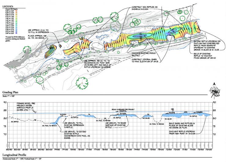
LMR 2002 Design 1
The concept guiding Design 1 was to attempt to divide the flow into distinct primary and secondary channels. To achieve this, two in-channel bars were designed. First, a small bar was placed right of center on the exit of the upper riffle to divide the flow ~60:40. Downstream of that a large streamlined bar was placed over the right half of the channel with a secondary channel at the far right. The large bar was intended to provide spawning habitat in the secondary channel, fry and spawning habitat on its top, and adult holding habitat in the constricted pool on river left.
The units in all plots below are American customary (ft, ft/s).
Depths over the bars were predicted to be 0- 1.5', with some drying out of the large bar at Q < 350 cfs.
Water was predicted to be effectively divided by the small bar with velocities of 2-3.5 ft/s, but the velocity in the secondary channel was a much lower 0.5 -2 ft/s. Peak velocities of 4-6 ft/s occurred where the primary channel was heavily constricted by the large island, so that could help provide for a self-sustainable pool at that location.
The predicted flow pattern shows that the large bar was designed too big, because very little water diverts into the secondary channel.
The predicted habitat benefit of design 1 did not meet expectations. The secondary channel was too slow for use as spawning habitat. However, the small bar did create a zone of high quality habitat. Along the flank of the large bar a zone of medium and high quality habitat was evident too.
8 mm gravels were predicted to be mobile through the constricted pool. Areas of intermittent scour occur around the small bar and downstream of the constricted pool.
32 mm gravels are predicted to be unlikely to scour anywhere on-site at this discharge, except in highly localized convective acceleration zones around feature protrusions and over the constricted pool.
The median particle size and coarser bed material sizes are predicted to be unlikely to mobilize anywhere on-site at this discharge, except in highly localized convective acceleration zones around feature protrusions. The images below show the results for 50, 64, and 128 mm, respectively downward.

LMR 2002 Design 2
concept guiding design 2 was to create a broad flat riffle with an elevation and slope optimized to give high quality riffle habitat. A pool constriction element was included to direct the thalweg. The potential pitfalls of this design include lack of cover and habitat heterogeneity elements, which some biologists claim are necessary for fish utilization. Also, habitat value at significantly different discharges than 335 cfs could be greatly diminished.
The units in all plots below are American customary (ft, ft/s).
Water depths over the upper riff le were a constant 1.5- 2', while over the channel constrict ion bar they were 1.25- 1.75'. These are ideal depths for spawning on the LMR.
The velocities over the upper riffle and peripheral bar were a steady, uniform 1.5-2 ft/s. A zone of 2.5-3 ft/s velocities occurs over the upper riffle exit and over the constricted pool.
The predicted flow pattern was not as expected. Because the peripheral bar had a uniform depth it did not yield a strong control on flow vectors. Instead, flow was directed according to the pre-existing bends of the degraded banks. However, since this pushed the flow right over the main riffle and bar areas, it yielded highly desirable depth and velocity conditions.
The predicted spawning habitat quality was tremendously improved over all areas of gravel fi ll accord ing to t his design. The upper riffle becomes uniformly high quality habitat, while the peripheral bar becomes medium quality habitat. The area of high quality habitat is also increased adjacent to the island.
8 mm and coarser-sized bed materials are predicted to be unlikely to scour for most of the reach at this discharge. The images below show the 8, 32, 50, 64, and 128 mm results in order downward.

LMR 2002 Design 3
The concept for Design 3 was to merge the best features of Designs 1 and 2, and to add boulder complexes for additional habitat heterogeneity. The upper riffle was heightened and lengthened as in Design 2, but then a bar was placed right of channel center to split the flow 60:40 as in Design 1. Then a central bar was placed downstream to yield a wide secondary ,channel. Downstream of that, gravel was added to enhance the area adjacent to the island to have more high quality spawning habitat. GraveI was also added to the downstream riffle to enhance its habitat as well, since this design was more gravel efficient than the previous two.
With is design was not expected to yield as optima I habitat from a GHSI perspective compared to Design 2, the idea was that habitat heterogeneity and hydrogeomorphic functionality should be considered along with GHSI.
The units in all plots below are American customary (ft, ft/s).
Depths over the upper half of the model area were predicted to be primarily in the 1-2' range, as desired. The two bars were both submerged and at a shallow depth suitable for rearing habitat. The downstream riffle was raised so its depth was also in the 1-2.5' range.
Velocity magnitude for the upper half of the model area was mostly in the 1-2.5 ft/s range as desired. The thalweg had velocities of 3.5-5 ft/s over constricted pools affected by bar and boulder placement, as expected. Velocity over the downstream riffle was also in the 1.5-2.5 ft/s range.
The predicted flow pattern yielded the desired effect of flow divergence over riffles and convergence over pools. The small bar and boulder complexes diverted flow into both the main constricted thalweg and the secondary channel. The secondary channel was now wide and fast enough to serve as potential spawning habitat. Downstream of the central bar, flow diverged onto the riffle area and then strongly converged into the pool, as desired for improved self-sustainability.
The predicted habitat quality for Design 3 indicates that this design would successfully improve all riffle and glide areas of the project site from predominantly low quality to medium and high quality spawning habitat. The central bar would provide rearing habitat while the enhanced pools would provide adult holding habitat. Areas of habitat heterogeneity degrade GHSI, but are expected to be "hot spots" of spawning activities (see Wheaton et al., 2004c) for evaluation of this prediction based on fish utilization data).
8 mm gravels were predicted to be mobile through the constricted pool and around some boulders.
32 mm and coarser-sized bed materials are predicted to be unlikely to scour for most of the reach at this discharge. The images below show the 32, 50, 64, and 128 mm results in order downward.
LMR 2002 As-Built Analysis
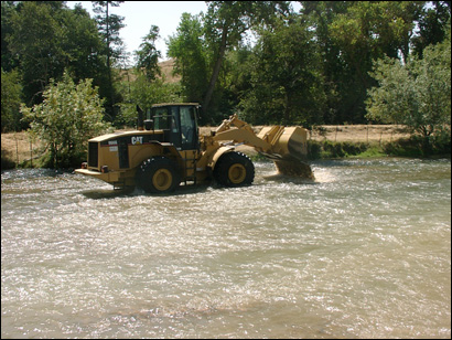
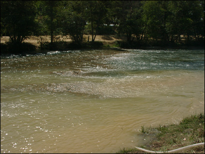
Design 3 was selected, so the post-project, as-built condition reflects that design, to the best that it could be built using a front loader with appropriate grading plans and elevation stakes. The riffle crest was shifted downstream a bit and was a bit higher than expected. Also, as in 2001, the riffle adjacent to the island was not built downstream as far as designed and its back-slope was too steep. The former poblem may be due to subsurface compaction consuming more gravel than expected. The latter problem is due to the fundamental limitation of the water depth a front loader can handle, so the back-slope will always be too steep with this method.
The units in all plots below are American customary (ft, ft/s).
Predicted water depths reveal significant bed diversity, including front- loader track imprints. Riffle areas had depths ranging from 0.5-1.5', as desired.
Predicted velocity magnitudes were 1.5·3 ft/s over riffles, except behind boulder complexes where they were 0-1 ft/s. Localized peak velocities of 4·6 ft/s occurred over the over-steepened riffle tail.
The predicted flow pattern yielded the desired effect of flow divergence over riffles and convergence over pools. The small bar and boulder complexes diverted flow into both the main constricted thalweg and the secondary channel. The secondary channel was now wide and fast enough to serve as potential spawning habitat . Downstream of the central bar, flow did not diverge much because the riffle ended too soon, but flow did strongly converged into the pool, as desired for improved self-sustainability.
The predicted post-project habitat quality indicates that the outcome was quite similar to that predicted for Design 3. More high quality habitat was obtain than expected in the primary channel adjacent to the central bar and over the downstream riffle, while less was obtained than expected form the riffle adjacent to the island where there was a gravel shortage and at the project entrance that was slightly shifted downstream.
8 mm gravels were predicted to be mobile on t he back-slope of the over-steepened riffle tail, around some boulders, and over portions of the downstream riffle crest.
32 mm and coarser-sized bed materials are predicted to be unlikely to scour for most of the reach at this discharge, except for a tiny portion of the over-steepened riffle tail. The images below show the 32, 50, 64, and 128 mm results in order downward.