LMR 1999 Site
LMR 1999 Preliminary Planning
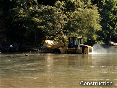
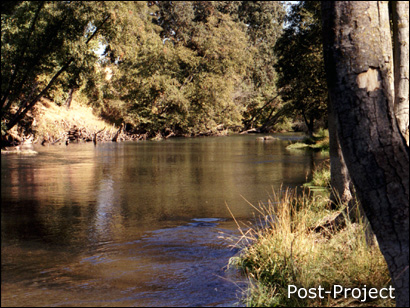
In fall 1999, EBMUD placed 2450 m3 of washed gravel (obtained from a nearby commercial floodplain mining operation) into the river below Camanche, creating exposed boulders, chutes, pools, and riffles. This volume was dictated by available funds for the project as opposed to being derived from sediment budget calculations. Preliminary planning for this project was done by EBMUD staff, and this was prior to initiating development of SHIRA.
LMR 1999 Data Collection
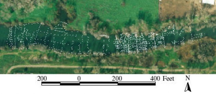
Channel topography, water depth, water surface elevation, velocity, and substrate sizes were measured on-site, both before and after the project was built. The majority of this work was done by EBMUD, with some hydraulic data collected by UC Davis. UC Davis used the field data to estimate 2D model parameters, including eddy viscosity and bed roughness. The image below shows 1,155 topographic surveying points (both pre- and post-project) overlain on the 1995 aerial image. As this was the first project done by the EBMUD-UCD collaboration, the scope of surveying was quite limited compared to how it progressed by 2001 and beyond.
LMR 1999 Design Concepts
Four alternative scenarios for 1999 gravel placement were designed to compare against the actual ad hoc placement. Given the numerous artificial degrees of freedom in designing alternative reach topography (c. 3^25,000), an objective search for the optimal solution to habitat goals and sediment entrainment constraints was not feasible. Instead, different channel configuration types were tested, including alternate bars, channel braid, alternate bars+braid, and flat riffle with boulders. All designs except the last used large, coherent bed features that were thought to offer high quality contiguous habitat while also limiting isolated protrusions susceptible to erosion. The downstream half of the model area encompassed a channel -wide pool that was kept because it was too deep to fill economically and it may provide habitat for other life stages of salmonids. Further, the pool also provided an opportunity to observe any possible important flow dynamics such as recirculating eddies that are zones of rapid change in flow velocity and direct ion that may provide rest sites for spawners. Bowl-shaped pool to riffle transitions were also considered beneficial, as they promote stream water downwelling, aid oxygenation of gravels, and are preferentially used by salmonids (Kondolf, 2000).
LMR 1999 Modeling
One aspect that sets SHIRA apart form other river rehabilitation frameworks is that it uses predictive 2D model ing to assess the design hypotheses used in each design scenario in terms of hydrodynamics, bed scour, and habitat availability.
In this area, 2D mode l predictions are presented for pre and post -project conditions as well as for conditions in 4 alternative designs. Models have been run for the spawning flow and for bankfull discharge, but only the former is presented here. Brief comments on each result are provided.
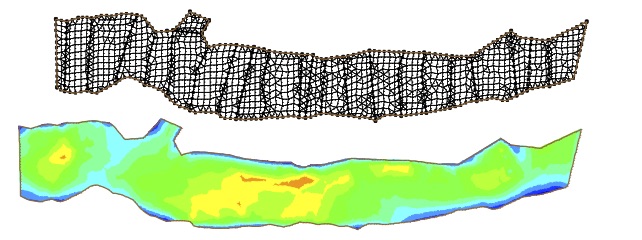
The image below shows the pre-project 2D computational mesh used in FESWMS. The mesh has 4888 nodes and 1513 elements. Elevation at each mesh node was interpolated from 807 points.
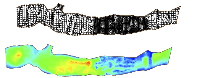
The image below shows the as-built 2D computational mesh used in FESWMS. The mesh has 7391 nodes and 2796 elements. Elevation at each mesh node was interpolated from 1155 points.You can see that from pre to post there had to be a substantial increase in resolution in the project area in order to capture the details of the features that were built. This is the main strength of 2D modeling, to be able to resolve such detail and use it to better explain sediment and fish behavior at the meter-resolution scale at which these functions occur.
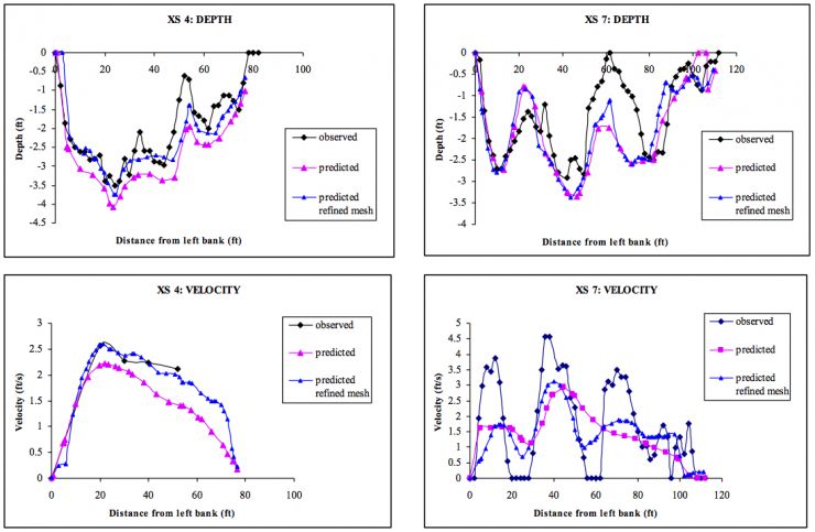
The image below shows results from XS-based 2D model validation. Black is observations, pink is initial modeling with a lower resolution mesh, and blue is final modeling with a refined mesh. We have come a long way with model performance compared to how it was back in 1999, but the fact remains that 2D models do struggle with getting the same strength of lateral shear that is observed in the field, because of the turbulence closure approach used.
LMR 199 Pre-Project Characterization
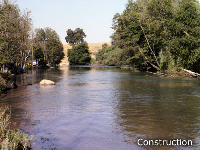
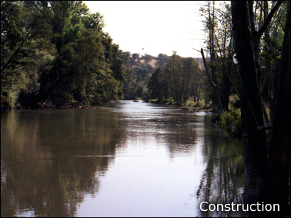
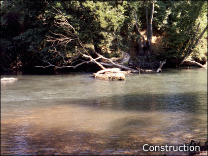
Prior to any spawning habitat rehabilitation, the river at this site consisted of a relatively homogenous glide ending in a deep mining hole.


LMR 1999 Design 1- Alternate Bars
This alternative scenario was built upon the topography from pre-gravel scenario conditions. Three alternate bars were created and gravel added throughout the replenishment area to decrease depths. The pre-existing pool feature within the replenishment area was retained and riffles spanning the entire channel stretched from alternate bar to alternate bar.

LMR 1999 Design 2- Split/Braided
In this scenario, a 76.2-m long, 5.18-m wide sinuous braid was placed in the center of the channel. Gravel was added to create riffle -pool- riffle sequences on both sides of the braid.
LMR 1999 Design 3- Alternate Bars + Split/Braided
Features from Designs 1 and 2 were combined in Design 3 to create two narrow meandering channels with in the replenishment area.

LMR 1999 Design 4- Flat With Boulders
For this scenario, gravel was first placed over the ent ire replenishment area to form a large riffle. Then, ten boulder features were distributed evenly over the river- left two-thirds of the scenario area. Boulders were generally 3 m in diameter. Boulder tops were dry at low flow. The right side of the channel had no boulders added.
LMR 1999 Ad Hoc As-Built Topo
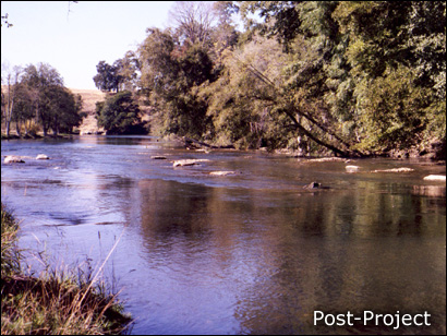
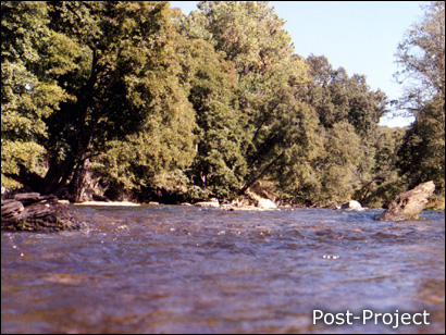
In the actual as-built topography (which was put in place before the four theoretical designed were even conceived as a thought experiment), gravel was added to the entire streambed to decrease water depths throughout the replenishment area. Several longitudinal bars were built along the left side of the channel to create fast-running chutes. Throughout the right side of the channel, gravel was scattered to create exposed point bars and riffles under low flow conditions. Exposed boulders were also used to create habitat features.